Water Flow Sensor Data Sheet

Least 6 from any fittings or valves that may change water direction flow rate or pipe diameter or no closer than 24 from a valve or drain.
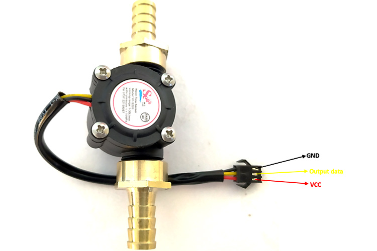
Water flow sensor data sheet. Metallic tee flow sensor 250 br. The hall effect sensor will then output a pulse width. 4 1 reading water flow rate with water flow sensor 4 1 1 hardware installation 4 1 2 programming 5 wiring diagram 6 output table 7 faq 8 support 9 version tracker 10 resource 11 see also 12 licensing 13 external links introduction water flow sensor consists of a plastic valve body a water rotor and a hall effect sensor. The data industrial series 228 250 flow sensors feature a six bladed impeller design with a proprietary non magnetic sensing mechanism.
When water flows through. From a valve or drain. Change water direction flow rate or pipe diameter or no closer than 24 in. It is usually used at the inlet end to detect the amount of flow.
Detectors shall have a sensitivity in the range of 4 to 10 gallons per minute and a static pressure rating of 450 psi for 2 in. The detector shall respond to waterflow in the specified. When liquid flows through the sensor a magnetic rotor will rotate and the rate of rotation will vary with the rate of flow. The yf s201 water flow sensor consists of a plastic valve body flow rotor and hall effect sensor.
Detectors shall have a sensitivity in the range of 4 to 10 gallons per minute and a static pressure rating of 250 psi. Product data sheet dimensions product overview 3315 g 3 series water sensor protect your home from expensive leaks and floods by installing a 3 series water sensor near water heaters drain pans and underneath sinks.


